FSI Tutorial 3d with pre_exodus and Cubit
Introduction
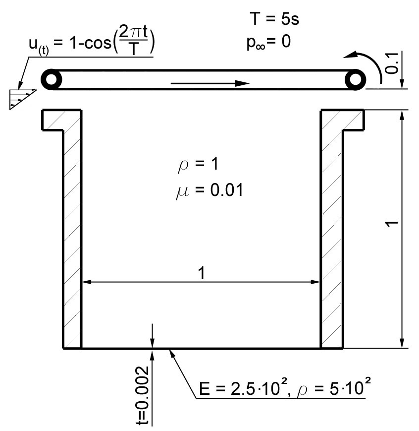
As example, we consider a 3d driven cavity example as sketched in the figure below with a depth of 0.05. Hint: In case you want or need to see a sample solution for this tutorial (the FSI part) you will find corresponding files in the 4C subfolder /tests/framework-tests/! However, it is highly recommended to look at these files only in case you encounter severe problems while stepping through the tutorial. For further details and references we refer the reader to [Wall99].
The driven cavity example
In the following, we first create the finite element mesh for the complete structure, but then we’ll split the simulation into three sections:
Structure part
Fluid part
Fluid-Structure interaction part
Creating the Geometry with Cubit
Besides meshing cubit also has several geometry creation methods. We refer to the provided manual and tutorials. It supports scripting (also Python), therefore we provide the following Journal-file containing the necessary geometry commands as well as mesh and definitions for elements and boundary conditions, respectively.
  1reset
  2$=======================Define parameters
  3# {Depth=0.05}
  4# {Width=1.0}
  5# {BottomHeight=0.002}
  6# {CavityHeight=1.0}
  7# {InflowHeight=0.1}
  8# {MeshDepth=1}
  9# {MeshWidth=32}
 10# {MeshBottomHeight=1}
 11# {MeshCavityHeight=32}
 12# {MeshInflowHeight=7}
 13
 14$$GEOMETRY
 15$=====================Create Bottom
 16brick x {Width} y {BottomHeight} z {Depth}
 17volume 1 move x {Width/2} y {-BottomHeight/2} z {-Depth/2}
 18$=====================Create Fluid Part
 19$ cavity + inflow
 20brick x {Width} y {CavityHeight+InflowHeight} z {Depth}
 21align volume 2 surface 9 with surface 5
 22$ divide cavity and inflow region
 23webcut volume 2 with plane yplane offset {CavityHeight} imprint merge
 24$$MESHING
 25$=======================Mesh Bottom
 26curve 3 interval {MeshBottomHeight}
 27curve 3 scheme equal
 28mesh curve 3
 29curve 2 interval {MeshWidth}
 30curve 2 scheme equal
 31mesh curve 2
 32curve 11 interval {MeshDepth}
 33curve 11 scheme equal
 34mesh curve 11
 35mesh volume 1
 36$=======================Mesh Cavity
 37curve 29 interval {MeshCavityHeight}
 38curve 29 scheme equal
 39mesh curve 29
 40curve 16 interval {MeshWidth}
 41curve 16 scheme equal
 42mesh curve 16
 43curve 21 interval {MeshDepth}
 44curve 21 scheme equal
 45mesh curve 21
 46mesh volume 2
 47$=======================Mesh Inflow
 48curve 40 interval {MeshInflowHeight}
 49curve 40 scheme equal
 50mesh curve 40
 51mesh volume 3
 52$$EXODUS - definitions
 53$=======================Structure
 54block 1 volume 1
 55block 1 name "flexible bottom"
 56nodeset 1 surface 4
 57nodeset 1 name "structure surface left"
 58nodeset 2 surface 6
 59nodeset 2 name "structure surface right"
 60nodeset 3 surface 1
 61nodeset 3 name "structure surface front"
 62nodeset 4 surface 2
 63nodeset 4 name "structure surface back"
 64nodeset 5 surface 5
 65nodeset 5 name "structure coupling surface"
 66nodeset 6 curve 3
 67nodeset 6 name "structure edge front left"
 68nodeset 7 curve 7
 69nodeset 7 name "structure edge back left"
 70nodeset 8 curve 5
 71nodeset 8 name "structure edge back right"
 72nodeset 9 curve 1
 73nodeset 9 name "structure edge front right"
 74$=======================Fluid
 75block 2 volume 2 3
 76block 2 name "fluid"
 77nodeset 10 surface 15
 78nodeset 10 name "cavity wall left"
 79nodeset 11 surface 17
 80nodeset 11 name "cavity wall right"
 81nodeset 12 surface 14 21
 82nodeset 12 name "fluid wall front"
 83nodeset 13 surface 16 20
 84nodeset 13 name "fluid wall back"
 85nodeset 14 surface 9
 86nodeset 14 name "fluid coupling surface"
 87nodeset 15 surface 11
 88nodeset 15 name "lid"
 89nodeset 16 surface 22
 90nodeset 16 name "inflow"
 91nodeset 17 surface 19
 92nodeset 17 name "outflow"
 93nodeset 18 curve 29
 94nodeset 18 name "cavity edge front left"
 95nodeset 19 curve 31
 96nodeset 19 name "cavity edge back left"
 97nodeset 20 curve 32
 98nodeset 20 name "cavity edge back right"
 99nodeset 21 curve 30
100nodeset 21 name "cavity edge front right"
101nodeset 22 curve 16
102nodeset 22 name "cavity edge front bottom"
103nodeset 23 curve 18
104nodeset 23 name "cavity edge back bottom"
105nodeset 24 curve 21
106nodeset 24 name "cavity edge left bottom"
107nodeset 25 curve 22
108nodeset 25 name "cavity edge right bottom"
109nodeset 26 curve 26
110nodeset 26 name "cavity-inflow edge"
111nodeset 27 curve 40
112nodeset 27 name "inflow edge front"
113nodeset 28 curve 39
114nodeset 28 name "inflow edge back"
115nodeset 29 curve 23
116nodeset 29 name "lid edge left"
117nodeset 30 curve 14
118nodeset 30 name "lid edge front"
119nodeset 31 curve 20
120nodeset 31 name "lid edge back"
121nodeset 32 vertex 12
122nodeset 32 name "cavity vertex front left bottom"
123nodeset 33 vertex 15
124nodeset 33 name "cavity vertex back left bottom"
125nodeset 34 vertex 14
126nodeset 34 name "cavity vertex back right bottom"
127nodeset 35 vertex 9
128nodeset 35 name "cavity vertex front right bottom"
129nodeset 36 vertex 19
130nodeset 36 name "cavity-inflow vertex front 1"
131nodeset 37 vertex 17
132nodeset 37 name "cavity-inflow vertex front 2"
133nodeset 38 vertex 11
134nodeset 38 name "lid vertex front left"
135nodeset 39 vertex 16
136nodeset 39 name "lid vertex back left"
137
138$======================= export mesh
139export mesh "tutorial_fsi_3d.e" block all dimension 3 overwrite
140
Within Cubit, open the Journal-Editor (Tools \(\to\) Journal
Editor), paste the text above and press play. For later usage it is
convenient to save the current content of the Journal-Editor into a *.jou file.
Export now the created geometry and mesh to an exodus-file of your choice,
let say, <yourmesh>.e via File \(\to\) Export….
During export, set the dimension explicitly to 3d.
Working with pre_exodus
pre_exodus is a C++ code embedded into the 4C environment. It is meant to transfer a given mesh into a 4C-readable input file. Information about this tool can be found in the Analysis Guide.
Besides a given mesh as the one we just created using CUBIT (see above), we need two more files:
the bc-file, which contains the specific element declaration and the particular boundary conditions, and
the header file, which contains the general parameters such as solvers, algorithmic parameters, etc..
In the following sections, we’ll learn how to create the these two files.
After creating the header and bc file, we may start the solver use the call
./4C <inputdirectory>/your_example.dat <outputdirectory>/outputprefix
(in the 4C-directory). The results are then written to the result directory with the prefix you chose. Note that a number of files are created with this prefix depending on the output you requested.
The Structure Part
In the following we will always refer to the same exodus-file of the whole geometry and mesh. For the different problems we differentiate between header-file and bc-file. We start with the pure structural simulation.
Header-file
Find the following sections in ’default.head’ and edit as given:
-----PROBLEM TYPEset
PROBLEMTYPE Structure-----STRUCTURAL DYNAMICset
DYNAMICTYPE GenAlphaset
LINEAR_SOLVER 1set
NUMSTEP 10set
TIMESTEP 0.5-----SOLVER 1set
NAME Solverset
SOLVER UMFPACK-----MATERIALSinsert
MAT 1 MAT_Struct_StVenantKirchhoff YOUNG 250.0 NUE 0.3 DENS 500
Safe the file under a different name, e.g. dc_struct.head.
bc-file
As mentioned above we create our bc-file from the ’default.bc’. This consists of a introduction part where some global mesh statistics are given, a couple of example entries for definitions, a list of all defined mesh entities in your mesh-file, and finally a list of all valid 4C conditions to choose from.
For our structure problem we will only define the corresponding mesh entities. They are easily identified by the names you have given in Cubit, e.g. “flexible bottom”, or “inflow”. You may notice that we do not assign any ’E’-entity-numbering. They are automatically determined in the order they appear in the bc-file. Therefore, if you want to change the numbering in the 4C input file, e.g. for correct hierarchy, you have to change the order in the bc-file.
Therefore we assign:
The structure elements
2Element Block, named: flexible_bottom
3of Shape: HEX8
4has 32 Elements
5*eb1="ELEMENT"
6sectionname="STRUCTURE"
7description="MAT 1 KINEM nonlinear TECH eas_full"
8elementname="SOLID"
Surface clamping conditions and fixtures (including hierarchical line conditions)
18Node Set, named: structure_surface_left
19Property Name: none
20has 4 Nodes
21*ns1="CONDITION"
22sectionname="DESIGN SURF DIRICH CONDITIONS"
23description="NUMDOF 3 ONOFF 1 1 1 VAL 0.0 0.0 0.0 FUNCT 0 0 0"
24
25Node Set, named: structure_surface_right
26Property Name: none
27has 4 Nodes
28*ns2="CONDITION"
29sectionname="DESIGN SURF DIRICH CONDITIONS"
30description="NUMDOF 3 ONOFF 1 1 1 VAL 0.0 0.0 0.0 FUNCT 0 0 0"
31
32Node Set, named: structure_surface_front
33Property Name: none
34has 66 Nodes
35*ns3="CONDITION"
36sectionname="DESIGN SURF DIRICH CONDITIONS"
37description="NUMDOF 3 ONOFF 0 0 1 VAL 0.0 0.0 0.0 FUNCT 0 0 0"
38
39Node Set, named: structure_surface_back
40Property Name: none
41has 66 Nodes
42*ns4="CONDITION"
43sectionname="DESIGN SURF DIRICH CONDITIONS"
44description="NUMDOF 3 ONOFF 0 0 1 VAL 0.0 0.0 0.0 FUNCT 0 0 0"
53Node Set, named: structure_edge_front_left
54Property Name: none
55has 2 Nodes
56*ns6="CONDITION"
57sectionname="DESIGN LINE DIRICH CONDITIONS"
58description="NUMDOF 3 ONOFF 1 1 1 VAL 0.0 0.0 0.0 FUNCT 0 0 0"
59
60Node Set, named: structure_edge_back_left
61Property Name: none
62has 2 Nodes
63*ns7="CONDITION"
64sectionname="DESIGN LINE DIRICH CONDITIONS"
65description="NUMDOF 3 ONOFF 1 1 1 VAL 0.0 0.0 0.0 FUNCT 0 0 0"
66
67Node Set, named: structure_edge_back_right
68Property Name: none
69has 2 Nodes
70*ns8="CONDITION"
71sectionname="DESIGN LINE DIRICH CONDITIONS"
72description="NUMDOF 3 ONOFF 1 1 1 VAL 0.0 0.0 0.0 FUNCT 0 0 0"
73
74Node Set, named: structure_edge_front_right
75Property Name: none
76has 2 Nodes
77*ns9="CONDITION"
78sectionname="DESIGN LINE DIRICH CONDITIONS"
79description="NUMDOF 3 ONOFF 1 1 1 VAL 0.0 0.0 0.0 FUNCT 0 0 0"
The later coupling surface is first loaded with constant vertical surface pressure
46Node Set, named: structure_coupling_surface
47Property Name: none
48has 66 Nodes
49*ns5="CONDITION"
50sectionname="DESIGN FSI COUPLING SURF CONDITIONS"
51description="coupling_id 1 "
Thus,
sectionnameanddescriptionhave to be changed for a pure solid simulation tosectionname="DESIGN SURF NEUMANN CONDITIONS" description="NUMDOF 3 ONOFF 0 1 0 VAL 0.0 -0.01 0.0 FUNCT 0 0 0 TYPE Live"
Delete the remaining items
eb2andns10tons39.
For Dirichlet conditions the first entry specifies the global degree of
freedom of the problem, denoted as \(n\). The \(n\) following
entries are the flags specifying which degrees of freedom are to be
prescribed in detail, where 1 means Dirichlet condition is applied
and 0 corresponds to a free degree of freedom. In structure
computations the flags two to four correspond to displacements in
\(x\), \(y\) and \(z\) direction, respectively. Flags five
to seven are ignored here. The next six entries of the description
specify the values of the prescribed displacements. Subsequently six
time dependent curve ids can be given, corresponding to the CURVE
section in the header-file. Finally six spatial function ids can be
defined, corresponding to the FUNCT section in the header-file.
CURVE and FUNCT are evaluated and their values are multiplied
with the values defined before.
Safe the file under a different name, e.g. ’dc_struct.bc’.
Creating 4C Input File and Running the Simulation
In a terminal, run the following command:
./pre_exodus --exo=dc.e --head=dc_struct.head --bc=dc_struct.bc --dat=dc_struct.dat
where the filenames might have to be replaced accordingly. This will
result in the specified dat-file which is already validated to be
accepted by 4C. However, if the file is meaningful cannot be assured.
Run the simulation by providing this dat-file and an output file to 4C and postprocess the results (refer to Working with PreExodus for the simulation, and to Post Processing for the post processing).
The Fluid Part
Again, we rely on the same mesh-file an edit ’default.head’ and ’default.bc’. We simulate a driven cavity with rigid bottom.
Header-file
Find the following sections in ’default.head’ and edit as given:
-----PROBLEM TYPEset
PROBLEMTYPE Fluid-----FLUID DYNAMICset
LINEAR_SOLVER 1set
NUMSTEP 100set
TIMESTEP 0.05-----SOLVER 1set
NAME Fluid solverset
SOLVER Belos-----MATERIALSinsert
MAT 1 MAT_fluid DYNVISCOSITY 0.01 DENSITY 1.0-----FUNCT 1insert
SYMBOLIC_FUNCTION_OF_SPACE_TIME (1-cos(2*t*pi/5))defining time-dependent inflow and lid movement-----FUNCT 2insert
SYMBOLIC_FUNCTION_OF_SPACE_TIME 10*(y-1)*(1-cos(2*t*pi/5))representing the spatial inflow distribution
Safe the file under a different name, e.g. ’dc_fluid.head’.
bc-file
For the pure fluid simulation we assign:
10Element Block, named: fluid
11of Shape: HEX8
12has 1248 Elements
13*eb2="ELEMENT"
14sectionname="FLUID"
15description="MAT 2 NA ALE"
16elementname="FLUID"
The boundary conditions are assigned as follows:
*ns10="CONDITION"    *No-Slip-Condition*
sectionname="DESIGN SURF DIRICH CONDITIONS"
description="NUMDOF 4 ONOFF 1 1 1 0 VAL 0.0 0.0 0.0 0.0 FUNCT 0 0 0 0"

*ns11="CONDITION"   *No-Slip-Condition*
sectionname="DESIGN SURF DIRICH CONDITIONS"
description="NUMDOF 4 ONOFF 1 1 1 0 VAL 0.0 0.0 0.0 0.0 FUNCT 0 0 0 0"

*ns12="CONDITION"`` Inplane Free-Slip-Condition
sectionname="DESIGN SURF DIRICH CONDITIONS"
description="NUMDOF 4 ONOFF 0 0 1 0 VAL 0.0 0.0 0.0 0.0 FUNCT 0 0 0 0"

*ns13="CONDITION"`` Inplane Free-Slip-Condition
sectionname="DESIGN SURF DIRICH CONDITIONS"
description="NUMDOF 4 ONOFF 0 0 1 0 VAL 0.0 0.0 0.0 0.0 FUNCT 0 0 0 0"

*ns14="CONDITION"`` No-Slip-Condition for pure fluid simulation
sectionname="DESIGN SURF DIRICH CONDITIONS"
description="NUMDOF 4 ONOFF 1 1 1 0 VAL 0.0 0.0 0.0 0.0 FUNCT 0 0 0 0"

*ns15="CONDITION"`` Driving lid, time dependent
sectionname="DESIGN SURF DIRICH CONDITIONS"
description="NUMDOF 4 ONOFF 1 1 1 0 VAL 1.0 0.0 0.0 0.0 FUNCT 1 0 0 0 "

*ns16="CONDITION"`` Inflow, time and space dependent
sectionname="DESIGN SURF DIRICH CONDITIONS"
description="NUMDOF 4 ONOFF 1 1 1 0 VAL 1.0 0.0 0.0 0.0 FUNCT 1 0 0 0"

*ns18="CONDITION"`` hierarchically corresponding line condition
sectionname="DESIGN LINE DIRICH CONDITIONS"
description="NUMDOF 4 ONOFF 1 1 1 0 VAL 0.0 0.0 0.0 0.0 FUNCT 0 0 0 0"

*ns19="CONDITION"`` hierarchically corresponding line condition
sectionname="DESIGN LINE DIRICH CONDITIONS"
description="NUMDOF 4 ONOFF 1 1 1 0 VAL 0.0 0.0 0.0 0.0 FUNCT 0 0 0 0"

*ns20="CONDITION"`` hierarchically corresponding line condition
sectionname="DESIGN LINE DIRICH CONDITIONS"
description="NUMDOF 4 ONOFF 1 1 1 0 VAL 0.0 0.0 0.0 0.0 FUNCT 0 0 0 0"

*ns21="CONDITION"`` hierarchically corresponding line condition
sectionname="DESIGN LINE DIRICH CONDITIONS"
description="NUMDOF 4 ONOFF 1 1 1 0 VAL 0.0 0.0 0.0 0.0 FUNCT 0 0 0 0"

*ns22="CONDITION"`` hierarchically corresponding line condition
sectionname="DESIGN LINE DIRICH CONDITIONS"
description="NUMDOF 4 ONOFF 1 1 1 0 VAL 0.0 0.0 0.0 0.0 FUNCT 0 0 0 0"

*ns23="CONDITION"`` hierarchically corresponding line condition
sectionname="DESIGN LINE DIRICH CONDITIONS"
description="NUMDOF 4 ONOFF 1 1 1 0 VAL 0.0 0.0 0.0 0.0 FUNCT 0 0 0 0"

*ns24="CONDITION"`` hierarchically corresponding line condition
sectionname="DESIGN LINE DIRICH CONDITIONS"
description="NUMDOF 4 ONOFF 1 1 1 0 VAL 0.0 0.0 0.0 0.0 FUNCT 0 0 0 0"

*ns25="CONDITION"`` hierarchically corresponding line condition
sectionname="DESIGN LINE DIRICH CONDITIONS"
description="NUMDOF 4 ONOFF 1 1 1 0 VAL 0.0 0.0 0.0 0.0 FUNCT 0 0 0 0"

*ns26="CONDITION"`` hierarchically corresponding line condition
sectionname="DESIGN LINE DIRICH CONDITIONS"
description="NUMDOF 4 ONOFF 1 1 1 0 VAL 0.0 0.0 0.0 0.0 FUNCT 0 0 0 0"

*ns27="CONDITION"`` hierarchically corresponding line condition
sectionname="DESIGN LINE DIRICH CONDITIONS"
description="NUMDOF 4 ONOFF 1 1 1 0 VAL 1.0 0.0 0.0 0.0 FUNCT 1 0 0 0"

*ns28="CONDITION"`` hierarchically corresponding line condition
sectionname="DESIGN LINE DIRICH CONDITIONS"
description="NUMDOF 4 ONOFF 1 1 1 0 VAL 1.0 0.0 0.0 0.0 FUNCT 1 0 0 0"

*ns29="CONDITION"`` hierarchically corresponding line condition
sectionname="DESIGN LINE DIRICH CONDITIONS"
description="NUMDOF 4 ONOFF 1 1 1 0 VAL 1.0 0.0 0.0 0.0 FUNCT 0 0 0 0"

*ns30="CONDITION"`` hierarchically corresponding line condition
sectionname="DESIGN LINE DIRICH CONDITIONS"
description="NUMDOF 4 ONOFF 1 1 1 0 VAL 1.0 0.0 0.0 0.0 FUNCT 0 0 0 0"

*ns31="CONDITION"`` hierarchically corresponding line condition
sectionname="DESIGN LINE DIRICH CONDITIONS"
description="NUMDOF 4 ONOFF 1 1 1 0 VAL 1.0 0.0 0.0 0.0 FUNCT 0 0 0 0"

*ns32="CONDITION"`` hierarchically corresponding point condition
sectionname="DESIGN POINT DIRICH CONDITIONS"
description="NUMDOF 4 ONOFF 1 1 1 0 VAL 0.0 0.0 0.0 0.0 FUNCT 0 0 0 0"

*ns33="CONDITION"`` hierarchically corresponding point condition
sectionname="DESIGN POINT DIRICH CONDITIONS"
description="NUMDOF 4 ONOFF 1 1 1 0 VAL 0.0 0.0 0.0 0.0 FUNCT 0 0 0 0"

*ns34="CONDITION"`` hierarchically corresponding point condition
sectionname="DESIGN POINT DIRICH CONDITIONS"
description="NUMDOF 4 ONOFF 1 1 1 0 VAL 0.0 0.0 0.0 0.0 FUNCT 0 0 0 0"

*ns35="CONDITION"`` hierarchically corresponding point condition
sectionname="DESIGN POINT DIRICH CONDITIONS"
description="NUMDOF 4 ONOFF 1 1 1 0 VAL 0.0 0.0 0.0 0.0 FUNCT 0 0 0 0"

*ns36="CONDITION"`` hierarchically corresponding point condition
sectionname="DESIGN POINT DIRICH CONDITIONS"
description="NUMDOF 4 ONOFF 1 1 1 0 VAL 0.0 0.0 0.0 0.0 FUNCT 0 0 0 0"

*ns37="CONDITION"`` hierarchically corresponding point condition
sectionname="DESIGN POINT DIRICH CONDITIONS"
description="NUMDOF 4 ONOFF 1 1 1 0 VAL 0.0 0.0 0.0 0.0 FUNCT 0 0 0 0"

*ns38="CONDITION"`` hierarchically corresponding point condition
sectionname="DESIGN POINT DIRICH CONDITIONS"
description="NUMDOF 4 ONOFF 1 1 1 0 VAL 1.0 0.0 0.0 0.0 FUNCT 1 0 0 0"

*ns39="CONDITION"`` hierarchically corresponding point condition
sectionname="DESIGN POINT DIRICH CONDITIONS"
description="NUMDOF 4 ONOFF 1 1 1 0 VAL 1.0 0.0 0.0 0.0 FUNCT 0 0 0 0"
Delete the remaining items eb1, ns17 and ns1 to ns9.
Fluid Dirichlet conditions differ from structure Dirichlet conditions only in the meaning of the first values. Instead of displacements, here velocities (two in 2d, three in 3d) and pressure values can be described.
Safe the file under a different name, e.g. dc_fluid.bc.
Creating 4C Input File and Running the Simulation
Again, we create the 4C input file by the command line tool
./pre_exodus --exo=dc.e --head=dc_fluid.head --bc=dc_fluid.bc --dat=dc_fluid.dat
where the filenames might have to be replaced accordingly.
This will result in the specified dat-file which is already validated to be accepted by 4C.
However, if the file is meaningful cannot be assured.
Run the simulation by providing this dat-file and an output file to 4C and postprocess the results (refer to FSI 3D Tutorial Postprocessing).
The FSI Part
Again, edit default.head as outlined below.
However to create the bc-file we copy
together the existing parts from dc_struct.bc and dc_fluid.bc and
change only the necessary coulping conditions as shown below.
header-file
Find the following sections in ’default.head’ and edit as given:
-----ALE DYNAMICset
LINEAR_SOLVER 1-----FLUID DYNAMICset
LINEAR_SOLVER 2-----FSI DYNAMICset
NUMSTEP = 50set
TIMESTEP = 0.1-----STRUCTURAL DYNAMICset
DYNAMICTYPE GenAlphaset
LINEAR_SOLVER 3-----MATERIALSinsert
MAT 1 MAT_Struct_StVenantKirchhoff YOUNG 1000.0 NUE 0.3 DENS 500insert
MAT 2 MAT_fluid DYNVISCOSITY 0.01 DENSITY 1.0insert
MAT 3 MAT_Struct_StVenantKirchhoff YOUNG 500.0 NUE 0.3 DENS 500-----CLONING MATERIAL MAPinsert
SRC_FIELD fluid SRC_MAT 2 TAR_FIELD ale TAR_MAT 3-----FUNCT1insert
SYMBOLIC_FUNCTION_OF_SPACE_TIME (1-cos(2*t*pi/5))defining time-dependent inflow and lid movement-----FUNCT2insert
SYMBOLIC_FUNCTION_OF_SPACE_TIME 10*(y-1)*(1-cos(2*t*pi/5))representing the spatial inflow distribution-----SOLVER 1set
NAME Ale solverset
SOLVER UMFPACK-----SOLVER 2set
NAME Fluid solverset
SOLVER Belos-----SOLVER 3set
NAME Structural solverset
SOLVER UMFPACK
Safe the file under a different name, e.g. ’dc_fsi.head’.
bc-file
We assume that you merged the fluid und structure bc-files, so the following entities have to be changed:
*eb1="ELEMENT"the structure elements with their materialsectionname="STRUCTURE" description="MAT 1 KINEM nonlinear TECH eas_full" elementname="SOLID"
*eb2="ELEMENT"the fluid elements with ALE and their materialsectionname="FLUID" description="MAT 2 NA ALE" elementname="FLUID"
*ns5="CONDITION"the coupling surface from the structure sidesectionname="DESIGN FSI COUPLING SURF CONDITIONS" description="coupling_id 1 "
*ns14="CONDITION"the coupling surface from the fluid sidesectionname="DESIGN FSI COUPLING SURF CONDITIONS" description="coupling_id 1 "
*ns22="CONDITION"release the ’coupling-line’ for inplane directionssectionname="DESIGN LINE DIRICH CONDITIONS" description="NUMDOF 4 ONOFF 0 0 1 0 VAL 0.0 0.0 0.0 0.0 FUNCT 0 0 0 0"
*ns23="CONDITION"release the ’coupling-line’ for inplane directionssectionname="DESIGN LINE DIRICH CONDITIONS" description="NUMDOF 4 ONOFF 0 0 1 0 VAL 0.0 0.0 0.0 0.0 FUNCT 0 0 0 0"
Further, you need to provide Dirichlet conditions to the automatically created ALE field. The displacement of the ALE field is restricted to zero at the left, right and top of the computational domain. At the front and the back plane, zero displacement in z-direction is demanded. Important: There are no Dirichlet conditions for ALE at the bottom of the cavity, since this is the FSI coupling interface. Thus, please add the following condition definitions to your new ’bc-file’:
*ns10="CONDITION"sectionname="DESIGN SURF ALE DIRICH CONDITIONS" description="NUMDOF 3 ONOFF 1 1 1 VAL 0.0 0.0 0.0 FUNCT 0 0 0 "
*ns11="CONDITION"sectionname="DESIGN SURF ALE DIRICH CONDITIONS" description="NUMDOF 3 ONOFF 1 1 1 VAL 0.0 0.0 0.0 FUNCT 0 0 0 "
*ns12="CONDITION"sectionname="DESIGN SURF ALE DIRICH CONDITIONS" description="NUMDOF 3 ONOFF 0 0 1 VAL 0.0 0.0 0.0 FUNCT 0 0 0 "
*ns13="CONDITION"sectionname="DESIGN SURF ALE DIRICH CONDITIONS" description="NUMDOF 3 ONOFF 0 0 1 VAL 0.0 0.0 0.0 FUNCT 0 0 0 "
*ns15="CONDITION"sectionname="DESIGN SURF ALE DIRICH CONDITIONS" description="NUMDOF 3 ONOFF 1 1 1 VAL 0.0 0.0 0.0 FUNCT 0 0 0 "
*ns16="CONDITION"sectionname="DESIGN SURF ALE DIRICH CONDITIONS" description="NUMDOF 3 ONOFF 1 1 1 VAL 0.0 0.0 0.0 FUNCT 0 0 0 "
*ns17="CONDITION"sectionname="DESIGN SURF ALE DIRICH CONDITIONS" description="NUMDOF 3 ONOFF 1 1 1 VAL 0.0 0.0 0.0 FUNCT 0 0 0 "
*ns18="CONDITION"hierarchically corresponding line conditionsectionname="DESIGN LINE ALE DIRICH CONDITIONS" description="NUMDOF 3 ONOFF 1 1 1 VAL 0.0 0.0 0.0 FUNCT 0 0 0 "
*ns19="CONDITION"hierarchically corresponding line conditionsectionname="DESIGN LINE ALE DIRICH CONDITIONS" description="NUMDOF 3 ONOFF 1 1 1 VAL 0.0 0.0 0.0 FUNCT 0 0 0 "
*ns20="CONDITION"hierarchically corresponding line conditionsectionname="DESIGN LINE ALE DIRICH CONDITIONS" description="NUMDOF 3 ONOFF 1 1 1 VAL 0.0 0.0 0.0 FUNCT 0 0 0 "
*ns21="CONDITION"hierarchically corresponding line conditionsectionname="DESIGN LINE ALE DIRICH CONDITIONS" description="NUMDOF 3 ONOFF 1 1 1 VAL 0.0 0.0 0.0 FUNCT 0 0 0 "
*ns24="CONDITION"hierarchically corresponding line conditionsectionname="DESIGN LINE ALE DIRICH CONDITIONS" description="NUMDOF 3 ONOFF 1 1 1 VAL 0.0 0.0 0.0 FUNCT 0 0 0 "
*ns25="CONDITION"hierarchically corresponding line conditionsectionname="DESIGN LINE ALE DIRICH CONDITIONS" description="NUMDOF 3 ONOFF 1 1 1 VAL 0.0 0.0 0.0 FUNCT 0 0 0 "
*ns26="CONDITION"hierarchically corresponding line conditionsectionname="DESIGN LINE ALE DIRICH CONDITIONS" description="NUMDOF 3 ONOFF 1 1 1 VAL 0.0 0.0 0.0 FUNCT 0 0 0 "
*ns27="CONDITION"hierarchically corresponding line conditionsectionname="DESIGN LINE ALE DIRICH CONDITIONS" description="NUMDOF 3 ONOFF 1 1 1 VAL 0.0 0.0 0.0 FUNCT 0 0 0 "
*ns28="CONDITION"hierarchically corresponding line conditionsectionname="DESIGN LINE ALE DIRICH CONDITIONS" description="NUMDOF 3 ONOFF 1 1 1 VAL 0.0 0.0 0.0 FUNCT 0 0 0 "
*ns29="CONDITION"hierarchically corresponding line conditionsectionname="DESIGN LINE ALE DIRICH CONDITIONS" description="NUMDOF 3 ONOFF 1 1 1 VAL 0.0 0.0 0.0 FUNCT 0 0 0 "
*ns30="CONDITION"hierarchically corresponding line conditionsectionname="DESIGN LINE ALE DIRICH CONDITIONS" description="NUMDOF 3 ONOFF 1 1 1 VAL 0.0 0.0 0.0 FUNCT 0 0 0 "
*ns31="CONDITION"hierarchically corresponding line conditionsectionname="DESIGN LINE ALE DIRICH CONDITIONS" description="NUMDOF 3 ONOFF 1 1 1 VAL 0.0 0.0 0.0 FUNCT 0 0 0 "
*ns36="CONDITION"hierarchically corresponding point conditionsectionname="DESIGN POINT ALE DIRICH CONDITIONS" description="NUMDOF 3 ONOFF 1 1 1 VAL 0.0 0.0 0.0 FUNCT 0 0 0 "
*ns37="CONDITION"hierarchically corresponding point conditionsectionname="DESIGN POINT ALE DIRICH CONDITIONS" description="NUMDOF 3 ONOFF 1 1 1 VAL 0.0 0.0 0.0 FUNCT 0 0 0 "
*ns38="CONDITION"hierarchically corresponding point conditionsectionname="DESIGN POINT ALE DIRICH CONDITIONS" description="NUMDOF 3 ONOFF 1 1 1 VAL 0.0 0.0 0.0 FUNCT 0 0 0 "
*ns39="CONDITION"hierarchically corresponding point conditionsectionname="DESIGN POINT ALE DIRICH CONDITIONS" description="NUMDOF 3 ONOFF 1 1 1 VAL 0.0 0.0 0.0 FUNCT 0 0 0 "
As any of these conditions matches an already defined NodeSet it will also match the corresponding ’E-id’ in the later 4C input file. Finally save the file under a different name, e.g. ’dc_fsi.bc’.
Creating 4C Input File and Running the Simulation
For a third time, run the command
./pre_exodus --exo=dc.e --head=dc_fsi.head --bc=dc_fsi.bc --dat=dc_fsi.dat
where the filenames might have to be replaced accordingly. This will
result in the specified dat-file which is already validated to be
accepted by 4C.
Run the simulation by providing the created dat-file and an output file to 4C and postprocess the results.
Postprocessing
You can postprocess your results with any visualization software you like. In this tutorial, we choose Paraview.
Before you can open the results, you have to generate a filter again. Call make post_drt_ensight in the 4C-directory. Filter your results in the output directory with the call
./post_drt_ensight --file=[outputdirectory]/outputprefix
After this open paraview, go to
File \(\to\) Open Data and select the filtered *.case file.
Only for older versions of Paraview:
Select the time step in the Select Time Value window on the left and
shift Byte order to little endian
Click on accept (or apply) to activate the display.
In the Display tab (section Color) you can choose now between Point pressure and Point velocity, whatever you want to display.
For the scale, activate the Scalar bar button in the View section.