3D Solid-State Battery Tutorial
This tutorial briefly introduces the setup of a simple 3D solid-state battery (SSB) problem. It aims to give an overview of the general workflow in 4C and show how to create a working input file. It is neither intended to be an introduction to the theory of the SSB model coupling solid mechanics (conservation of momentum) and electrochemistry (conservation of charge and mass), nor to demonstrate all possible optional settings for an SSB problem. For details on the theory, please refer to Schmidt et al. 2023, doi: 10.1016/j.cma.2023.116468.
Overview
Problem description
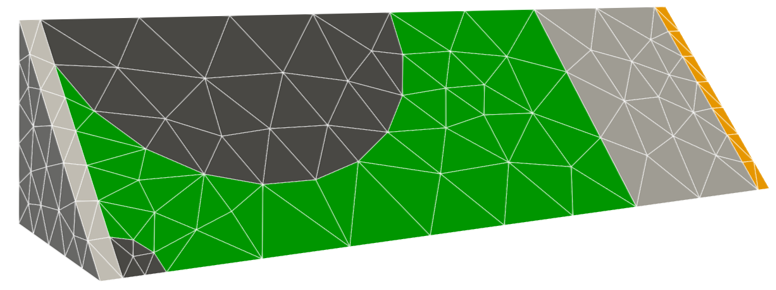
This tutorial uses a simplified geometry of a solid-state battery (SSB). From left to right, the SSB geometry consists of the cathode-side current collector (grey), the cathode active material particles (dark grey), the solid electrolyte (green), the lithium metal anode (light grey), and the anode-side current collector (orange) as depicted in the figure. A constant current charge process starts from a completely discharged state, while the mechanical boundary conditions fix the volume.
Here is an interactive version of the mesh where you can explore the mesh on your own by rotating and zooming:
Input files
For a valid input two files are needed in this case:
.exo/.efile containing the geometry and mesh (see Definition of the geometry for more details).4C.yamlfile containing all relevant parameters for the simulation (refer to the other subsections for more information)
Definition of the geometry
Information on the geometry and mesh are passed on to 4C as part of a binary EXODUS file (.e). This file can be
generated using the pre-processing software Cubit. Before we can export an EXODUS file from Cubit (File -> Export ->
Files of type: .e), we need to specify the geometry and meshing parameters in Cubit. This can be done using the GUI or
read from a journal file (.jou) containing the specific Cubit commands. A tutorial on how to use the Cubit GUI can be
found on the Coreform webpage and can be useful to get to
know some of the basic functionalities. The syntax of a Cubit command to a corresponding Input using the GUI can be seen
in the Cubit terminal.
Remark: After learning the syntax of the basic Cubit commands, it may be more convenient to exclusively use journal files for an easy adaptation and reproduction of your geometry and/or use in e.g. python scripts for parameter studies etc.
In tutorial_battery.jou, it can be seen that apart from the basic geometry definition and meshing, nodesets and
element blocks are assigned to the corresponding nodes/lines/surfaces/volumes. The nodesets are used later to assign the
boundary conditions, whereas the element blocks are used to assign material properties or conditions applied to volumes.
The last line in the journal file includes a terminal command to export the .exo/.e file from Cubit.
The journal file can be called in Cubit from the Terminal with the command
/path/to/cubit/executable -nographics /path/to/tutorial_battery.jou
This saves an EXODUS file in the current work directory. We refer to this file in our main input
file in the section STRUCTURE GEOMETRY as follows:
STRUCTURE GEOMETRY:
  FILE: tutorial_battery.e
  SHOW_INFO: summary
  ELEMENT_BLOCKS:
  - NAME: anode
    SOLIDSCATRA:
      TET4:
        MAT: 12
        KINEM: nonlinear
        TYPE: ElchElectrode
  - NAME: electrolyte
    SOLIDSCATRA:
      TET4:
        MAT: 8
        KINEM: nonlinear
        TYPE: ElchDiffCond
  - NAME: cathode
    SOLIDSCATRA:
      TET4:
        MAT: 2
        KINEM: nonlinear
        TYPE: ElchElectrode
  - NAME: anode_cc
    SOLIDSCATRA:
      TET4:
        MAT: 16
        KINEM: nonlinear
        TYPE: ElchElectrode
  - NAME: cathode_cc
    SOLIDSCATRA:
      TET4:
        MAT: 20
        KINEM: nonlinear
        TYPE: ElchElectrode
Definition of the materials
All materials are defined in the MATERIALS section of the input file. Please note that as we perform a coupled
simulation considering electrochemistry and solid mechanics materials for both fields have to be prescribed.
Which material is assigned to which entity for the solid mechanics problem can be found in the section
STRUCTURE GEOMETRY:
STRUCTURE GEOMETRY:
  FILE: tutorial_battery.e
  SHOW_INFO: summary
  ELEMENT_BLOCKS:
  - NAME: anode
    SOLIDSCATRA:
      TET4:
        MAT: 12
        KINEM: nonlinear
        TYPE: ElchElectrode
  - NAME: electrolyte
    SOLIDSCATRA:
      TET4:
        MAT: 8
        KINEM: nonlinear
        TYPE: ElchDiffCond
  - NAME: cathode
    SOLIDSCATRA:
      TET4:
        MAT: 2
        KINEM: nonlinear
        TYPE: ElchElectrode
  - NAME: anode_cc
    SOLIDSCATRA:
      TET4:
        MAT: 16
        KINEM: nonlinear
        TYPE: ElchElectrode
  - NAME: cathode_cc
    SOLIDSCATRA:
      TET4:
        MAT: 20
        KINEM: nonlinear
        TYPE: ElchElectrode
In addition, the assignment of the materials characterizing the electrochemistry can be found in the section
CLONING MATERIAL MAP:
CLONING MATERIAL MAP:
- SRC_FIELD: structure
  SRC_MAT: 2
  TAR_FIELD: scatra
  TAR_MAT: 1
- SRC_FIELD: structure
  SRC_MAT: 8
  TAR_FIELD: scatra
  TAR_MAT: 5
- SRC_FIELD: structure
  SRC_MAT: 12
  TAR_FIELD: scatra
  TAR_MAT: 11
- SRC_FIELD: structure
  SRC_MAT: 16
  TAR_FIELD: scatra
  TAR_MAT: 15
- SRC_FIELD: structure
  SRC_MAT: 20
  TAR_FIELD: scatra
  TAR_MAT: 19
While these two parts of the input file assign the corresponding material ID to each geometric entity for the solid
mechanics and the electrochemical fields, the actual definition of the materials with the corresponding parameters
happens in the MATERIALS section.
Definition of the boundary conditions
For the electrochemical field it needs to be stated that the conservation of charge and mass is considered, thus two degrees of freedom (dof) are solved for within this field. The first dof represents the conservation of mass (concentration of lithium or lithium-ions) and the second one represents the conservation of charge (electric potential).
A reference potential of 0V is set at the anode-side current collector using a Dirichlet boundary condition:
DESIGN SURF TRANSPORT DIRICH CONDITIONS:
- NODE_SET_NAME: surface_normal_z_an_cc
  NUMDOF: 2
  ONOFF:
  - 0
  - 1
  VAL:
  - 0
  - 0
  FUNCT:
  - 0
  - 0
and a constant current charge process is performed by assigning a Neumann boundary condition ot the cathode-side current collector:
DESIGN SURF TRANSPORT NEUMANN CONDITIONS:
- NODE_SET_NAME: surface_normal_z_cat_cc
  NUMDOF: 2
  ONOFF:
  - 0
  - 1
  VAL:
  - 0
  - 5.839316572e-06
  FUNCT:
  - null
  - null
For the solid mechanics field the conservation of linear (and angular) momentum is considered. The mechanical boundary
conditions are set such that the volume of the sample cannot change. This is achieved by the application of the
DESIGN * DIRICH CONDITIONS where * represents POINT, LINE, SURF.
Definition of the interface conditions
At the interface between electrode active material and solid electrolyte mesh tying is assumed. This means that the
domains cannot separate from each other, even under tensile stresses.
This is achieved by the application of the DESIGN SSI INTERFACE MESHTYING SURF CONDITIONS. Since we solve for a
coupled solid mechanics-electrochemistry problem we also need to provide interface conditions for the electrochemical
field. These are defined using the DESIGN S2I KINETICS SURF CONDITIONS, where a constant interface resistance
is applied between the electrode active materials and their adjacent current collectors. Moreover, the so-called
Butler-Volmer interface kinetics are applied to the interface of electrode active materials and solid electrolyte.
Finally, no interface flux is allowed between the solid electrolyte and the cathode-side current collector.
Specification of the simulation settings
Since we solve a coupled solid mechanics - electrochemistry (i.e. scalar transport) problem, we need to choose the corresponding problem type:
PROBLEM TYPE:
  PROBLEMTYPE: Structure_Scalar_Interaction
and set parameters in the respective sections. General settings concerning the output format are listed in the
sections prefixed with IO, e.g., the output settings for the solid mechanics problem are given as:
IO/RUNTIME VTK OUTPUT/STRUCTURE:
  OUTPUT_STRUCTURE: true
  DISPLACEMENT: true
  STRESS_STRAIN: true
These settings mean that output for the solid mechanics problem shall be written. More specifically, the displacement and the mechanical stresses are be written to the output.
General settings on the number of time steps, the time step sizes and information on the interaction of the solid mechanics and electrochemistry fields are listed in:
SSI CONTROL:
  NUMSTEP: 2
  MAXTIME: 2.0e7
  TIMESTEP: 10.0e3
  COUPALGO: ssi_Monolithic
  SCATRATIMINTTYPE: Elch
and the corresponding subsections.
Moreover, more detailed settings concerning the solid mechanics field are given in the STRUCTURAL DYNAMIC section
and subsections, while the more detailed settings for the electrochemistry field are presented in the
SCALAR TRANSPORT DYNAMIC section and subsections, as well as in ELCH CONTROL.
Run Simulation
Again, following the instructions from the README.md, the 4C
executable can be invoked with the tutorial_contact_3d.4C.yaml input file to run the solid-state battery simulation.